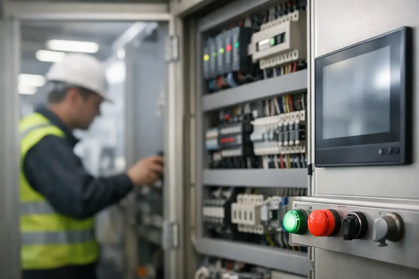
Controls Panel Design Standards That Reduce Downtime
A control panel failure rarely starts as a major event. It starts with a loose terminal, an overloaded 24 VDC supply, an unlabeled field wire, excessive heat, or a technician forced to troubleshoot around a poorly arranged enclosure. Controls panel design standards provide the framework for avoiding those failure points before the system reaches the plant floor.
For industrial operators, panel standards are not just a documentation requirement or a checkbox for an inspection. They affect commissioning time, maintenance response, electrical safety, spare-parts planning, future expansion, and the ability to recover from a fault without taking down an entire operation. A well-designed panel gives maintenance personnel a clear, safe path to diagnose and restore equipment. A poorly designed one turns routine faults into extended downtime.
Controls Panel Design Standards Start With Scope
There is no single standard that governs every industrial control panel. The correct design basis depends on the equipment, installation location, available fault current, customer specifications, electrical supply, safety functions, and authority having jurisdiction.
In the United States, UL 508A is commonly used for industrial control panel construction and listing. NFPA 79 applies to electrical equipment of industrial machinery, while the National Electrical Code, or NEC, governs installation requirements. NFPA 70E addresses electrical safety work practices, including arc-flash risk and safe maintenance procedures. For machinery with safety-related controls, ISO 13849-1 or IEC 62061 may be relevant to the safety function design and validation.
These documents overlap in practical ways, but they do not replace one another. A UL 508A-built panel may still need to meet a machine builder's NFPA 79 requirements, a facility's internal electrical specifications, and local code requirements. For equipment installed outside the United States or supplied to a global OEM, IEC 60204-1 and regional certification requirements may also apply.
The first engineering task is to define the applicable standards and the intended use of the panel. This should happen before component selection, not after fabrication. Waiting until final inspection to address SCCR, wire sizing, enclosure ratings, or safety circuit requirements is costly and often forces redesign.
Build for Safe Isolation and Fast Troubleshooting
A panel should make electrical isolation clear and controlled. The main disconnect must be correctly rated, accessible, lockable where required, and coordinated with the incoming supply. Maintenance teams need to know what the disconnect isolates and what circuits, if any, remain energized from separate sources such as UPS systems, external control power, generator feeds, or network equipment.
Control circuits need the same level of attention. A technician should be able to identify 120 VAC, 24 VDC, safety power, analog signals, motion power, and network circuits without tracing every wire by hand. Clearly separated voltage classes reduce troubleshooting time and lower the risk of accidental contact or incorrect meter use.
Circuit protection should be selective and documented. A single fault on a photoeye, solenoid bank, or remote I/O drop should not unnecessarily disable the PLC, HMI, safety controller, or an entire conveyor zone. Proper branch protection, fused terminal blocks where appropriate, electronic circuit protection, and alarm feedback can help isolate faults to the affected device.
This does not mean every circuit needs a complex protection scheme. The right approach depends on the machine and the consequences of a failure. A small standalone station may be simple. A high-throughput packaging line or distribution conveyor system often benefits from more granular protection because a minor field fault can otherwise interrupt a much larger process.
Design for Lockout, Verification, and Access
Safe access is part of panel design, not an afterthought. Provide adequate working space around disconnects, power supplies, drives, terminals, and field wiring. Components that require regular service should not be buried behind unrelated devices or installed where removal requires disturbing critical wiring.
Door-mounted components need flexible wiring, proper strain relief, and enough service loop to allow the door to open fully. Interlocks, disconnect handles, and internal mechanisms must operate as intended after final assembly. If a panel includes stored energy, such as VFD DC buses, the design and labeling should make discharge time and verification requirements clear.
Control Heat, Space, and Electrical Noise
Thermal management is one of the most common gaps in control panel design. PLCs, power supplies, VFDs, servo drives, network switches, transformers, and braking resistors all produce heat. If enclosure temperature exceeds component ratings, the result may be intermittent faults, shortened component life, communication failures, or nuisance drive trips.
Start with an actual heat-load calculation rather than assuming a larger enclosure will solve the problem. Consider ambient temperature, solar exposure, washdown conditions, enclosure material, ventilation restrictions, and heat generated by every installed device. Then select ventilation, filtered fans, air conditioning, heat exchangers, or enclosure cooling that fits the environment and maintenance capability of the facility.
Space planning matters just as much. Panels need room for wiring bends, terminal access, heat dissipation, future modifications, and replacement components. Packing an enclosure to its physical limit can lower initial cost but makes every future repair slower and more error-prone.
Electrical noise should be managed through physical separation and correct grounding practices. Keep high-voltage motor conductors, VFD output leads, and brake wiring away from low-level analog, encoder, and communication wiring. Use shielded cable where required by the device manufacturer, terminate shields correctly, and maintain a consistent grounding strategy. Random shield terminations and improvised grounding create hard-to-find problems, especially on systems with Ethernet/IP, PROFINET, remote I/O, motion control, or sensitive analog instrumentation.
Use Components That Support the Required SCCR
Short-circuit current rating is not a label to add at the end of a project. The SCCR of an industrial control panel must be established from the components and protective devices used in the power circuit. Available fault current at the installation point must also be known or verified.
A panel with a 5 kA SCCR may be unacceptable in a facility where available fault current is substantially higher. Raising panel SCCR may require different components, current-limiting fuses, tested combinations, or changes to the feeder protection. These decisions affect cost, lead time, and layout, which is why they belong in the initial design review.
This is especially relevant during modernization. Replacing a legacy starter bucket, adding a VFD, or installing a new control enclosure on an existing production line can change the fault-current assumptions. Do not assume the old panel label or original drawings still represent the installation.
Make Wiring and Documentation Serviceable
Good wiring practices are simple to recognize in the field. Conductors are labeled at both ends. Terminal blocks are numbered logically. Wire colors are consistent with the project standard. Spare terminals, spare conductors, and spare I/O capacity are intentional rather than accidental.
Drawings should match the built panel. That includes power schematics, control schematics, panel layouts, network architecture, I/O lists, terminal schedules, bill of materials, and safety circuit documentation. For PLC-based systems, the final package should also identify controller hardware, firmware revisions, program backup location, HMI application version, drive parameters, and managed-switch configuration where applicable.
Documentation becomes more valuable after commissioning, when the people who built the system are no longer standing next to it. During a 2 a.m. production interruption, a maintenance technician needs accurate information immediately. A marked-up print hidden in the panel door is better than nothing, but a controlled and current documentation package is the standard to aim for.
Leave Capacity for the Next Change
Industrial systems change. A conveyor gains an accumulation zone. A bakery line adds inspection equipment. A warehouse adds scanners, sortation controls, or new safety devices. Designing with no spare DIN rail, no spare terminals, no spare network ports, and no available I/O guarantees an expensive retrofit later.
The right amount of spare capacity depends on the application and project budget. Not every panel needs 30 percent unused space. But critical systems should have a realistic expansion plan, particularly where shutdown windows are limited and future modifications will occur under production pressure.
Validate Safety Functions as a Complete System
Safety circuits cannot be evaluated only by checking whether an emergency stop button opens a contact. The complete safety function must be defined and validated: the initiating device, safety relay or safety PLC logic, output devices, controlled stop behavior, feedback monitoring, reset logic, and the actual reduction of hazardous energy.
For example, an emergency stop on a conveyor may require a controlled stop through a VFD, followed by prevention of restart until reset conditions are met. A guard switch may require a different response than a rope pull or a light curtain. The required performance level or SIL depends on the risk assessment and the machine function.
Safety design also needs to account for bypasses, manual modes, maintenance functions, and communication failures. These are common places for unintended behavior to appear during commissioning. Functional safety documentation, validation records, and clear panel labeling help ensure the installed system matches the approved design.
Treat the Panel as an Uptime Asset
The best panel design is not necessarily the one with the lowest fabrication cost. It is the design that fits the environment, meets applicable requirements, can be maintained safely, and supports reliable production over its service life.
For legacy upgrades, that may mean retaining proven field devices while replacing an obsolete PLC and adding properly documented remote I/O. For a new machine, it may mean investing in better thermal design, managed networking, segregated power distribution, and spare capacity from the start. The right decision depends on operating risk, maintenance resources, and the cost of downtime.
Before releasing a panel for fabrication, walk through the likely failure scenarios with the people who will support it. Ask how they will isolate power, find a fault, replace a device, verify safety, and return the equipment to service. If those answers are clear on paper and practical at the enclosure, the panel is positioned to support production when it matters most.


Comments